
Logical Architecture
What is the Logical Architecture? And Layers?
The logical architecture is the large-scale organization of the software classes into packages (or namespaces), subsystems, and layers. It's called the logical architecture because there's no decision about how these elements are deployed across different operating system processes or across physical computers in a network(these latter decisions are part of the deployment architecture).
A layer is a very coarse-grained grouping of classes, packages, or subsystems that has cohesive responsibility for a major aspect of the system. Also, layers are organized such that"higher" layers (such as the UI layer) call upon services of"lower" layers, but not normally vice versa. Typically layers in anOO system include:
In a strict layered architecture, a layer only calls upon the services of the layer directly belowit. This design is common in network protocol stacks, but not in information systems, which usually have a relaxed layered architecture, in which a higher layer calls upon several lower layers. For example, the UI layer may call upon its directly subordinate application logic layer, and also upon elements of a lower technical service layer, for logging and so forth.
A logical architecture doesn't have to be organized in layers. But it's very common, and hence, introduced at this time.
Whatis Software Architecture?
An architecture is the set of significant decisions about the organization of a software system, the selection of the structural elements and their interfaces by which the system is composed, together with their behavior as specified in the collaborations among those elements, the composition of these structural and behavioral elements into progressively larger subsystems, and the architectural style that guides this organization these elements and their interfaces, their collaborations, and their composition.
Applying UML:Package Diagrams
UML package diagrams are often used to illustrate the logical architecture of a system the layers, subsystems,packages (in the Java sense), etc. A layer can be modeled as a UML package; for example, the UI layer modeled as a package named UI.
A UML package diagram provides a way to group elements. A UML package can group anything: classes, other packages, use cases, and so on. Nesting packages is very common. A UML package is a more general concept than simply a Java package or .NET namespace, though a UML package can represent those and more.
The package name may be placed on the tab if the package shows inner members, or on the main folder, if not.
It is common to want to show dependency(a coupling) between packages so that developers can see the large-scale coupling in the system. The UML dependency line is used for this, a dashed arrowed line with the arrow pointing towards the depended-on package.
A UML package represents a namespace so that, for example, a Date class may be defined in two packages. If you needto provide fully-qualified names, the UMLnotation is, for example, java::util::Date inthe case that there was an outer package named "java" with a nestedpackage named "util" with a Dateclass.
The UML provides alternate notations to illustrate outer and inner nested packages. Sometimes it is awkward to draw an outer package box around inner packages. Alternatives are shown in Figure 13.3.
Figure 13.3. Alternate UML approaches to showpackage nesting, using embedded packages, UML fully-qualified names, and thecircle-cross symbol.

Design with Layers
The essential ideas of using layers [BMRSS96]are simple:
· Organize the large-scale logical structure of a system into discrete layers of distinct, related responsibilities, with a clean, cohesive separation of concerns such that the "lower" layers are low-level and general services, and the higher layers are more application specific.
· Collaboration and coupling is from higher to lower layers;lower-to-higher layer coupling is avoided.
Using layers helps address several problems:
· Source code changes are rippling throughout the system many parts of the systems are highly coupled.
· Application logic is intertwined with the user interface, so it cannot be reused with a different interface or distributed to another processing node.
· Potentially general technical services or business logic is intertwined with moreapplication-specific logic, so it cannot be reused, distributed to another node, or easily replaced with a different implementation.
· There is high coupling across different areas of concern. It is thus difficult to divide the work along clear boundaries for different developers.
· The purpose and number of layers varies across applications and application domains(information systems, operating systems, and so forth). Applied to informationsystems, typical layers are illustrated and explained in Figure 13.4.
Figure 13.4.Common layers in an information system logical architecture.

Benefits of Using Layers
· Ingeneral, there is a separation of concerns, a separation of high from low-levelservices, and of application-specific from general services. This reduces coupling and dependencies, improves cohesion, increases reuse potential, and increases clarity.
· Related complexity is encapsulated and decomposable.
· Some layers can be replaced with new implementations. This is generally not possiblefor lower-level Technical Service or Foundation layers (e.g., java.util), but may be possible for UI, Application,and Domain layers.
· Lowerlayers contain reusable functions.
· Somelayers (primarily the Domain and Technical Services) can be distributed.
· Development by teams is aided because of the logical segmentation.
Cohesive Responsibilities; Maintain a Separation of Concerns
The responsibilities of the objects in a layer should be strongly related to each other and should not be mixed with responsibilities of other layers. For example, objects in the UI layer should focus on UI work, such as creating windows and widgets, capturing mouse and keyboard events, and so forth. Objects in the application logic or"domain" layer should focus on application logic, such as calculatinga sales total or taxes, or moving a piece on a game board.
UI objects should not do application logic. For example, a Java Swing JFrame (window)object should not contain logic to calculate taxes or move a game piece. And onthe other hand, application logic classes should not trap UI mouse or keyboardevents. That would violate a clear separation ofconcerns and maintaining high cohesion basicarchitectural principles.
Mapping Code Organization to Layers and UML Packages
Most popular OO languages (Java, C#, C++,Python, …) provide support for packages (called namespaces in C# and C++).
Here's an example, using Java, formapping UML packages to code. The layers and packages illustrated in Figure13.2 can map to Java package names as follows. Notice that the layer name isused as a section of the Java package name:
// --- UI Layer
com.mycompany.nextgen.ui.swing
com.mycompany.nextgen.ui.web
// --- DOMAIN Layer
// packagesspecific to the NextGen project
com.mycompany.nextgen.domain.sales
com.mycompany.nextgen.domain.payments
// --- TECHNICAL SERVICES Layer
// ourhome-grown persistence (database) access layer
com.mycompany.service.persistence
// thirdparty
org.apache.log4j
org.apache.soap.rpc
// --- FOUNDATION Layer
//foundation packages that our team creates
com.mycompany.util
Notice that, to support cross-project reuse, we avoided using a specific application qualifier ("nextgen")in the package names unless necessary. The UI packages are related to theNextGen POS application, so they are qualified with the application name com.mycompany.nextgen.ui.*. But the utilities we writecould be shared across many projects, hence the package name com.mycompany.utils, not com.mycompany.nextgen.utils.
Domain Layer vs.Application Logic Layer; Domain Objects
This section describes a simple but key concept in OO design!
A typical software system has UI logicand application logic, such as GUI widget creation and tax calculations. Now,here's a key question:
How do we design the application logicwith objects?
We could create one class called XYZ and put all the methods, for all the requiredlogic, in that one class. It could technically work (though be a nightmare tounderstand and maintain), but it isn't the recommended approach in the spiritof OO thinking.
So, what is the recommended approach?Answer: To create software objects with names and information similar to thereal-world domain, and assign application logic responsibilities to them. Forexample, in the real world of POS, there are sales and payments. So, insoftware, we create a Sale and Payment class, and give them application logicresponsibilities. This kind of software object is called a domain object. It represents a thing in the problemdomain space, and has related application or business logic, for example, a Sale object being able to calculate its total.
Designing objects this way leads to theapplication logic layer being more accurately called the domain layer of the architecture the layer thatcontains domain objects to handle application logic work.
What's the Relationship Between the Domain Layer and Domain Model?
This is another key point: There's arelationship between the domain model and the domain layer. We look to the domain model (which is a visualization of noteworthy domain concepts) forinspiration for the names of classes in the domain layer. See Figure 13.5.
Figure 13.5. Domain layer and domain model relationship.
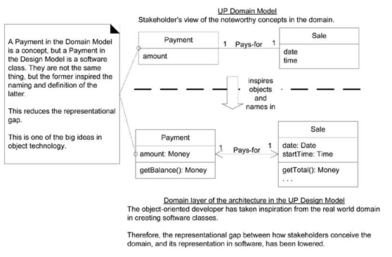
The domain layer is part of the software and the domain model is part of the conceptual-perspective analysis they aren'tthe same thing. But by creating a domain layer with inspiration from the domainmodel, we achieve a lower representational gap,between the real-world domain, and our software design. For example, a Sale in the UP Domain Model helps inspire us toconsider creating a software Sale class in thedomain layer of the UP Design Model.
Tiers, Layers, and Partitions
The original notion of a tier in architecture was a logical layer, not aphysical node, but the word has become widely used to mean a physicalprocessing node (or cluster of nodes), such as the "client tier" (theclient computer). This book will avoid the term for clarity, but bear this inmind when reading architecture literature.
The layersof an architecture are said to represent the vertical slices, while partitions represent a horizontal division ofrelatively parallel subsystems of a layer. For example, the Technical Services layer may be divided intopartitions such as Security and Reporting (Figure13.6).
Figure 13.6.Layers and partitions.

Don't ShowExternal Resources as the Bottom Layer
Most systems rely on external resourcesor services, such as a MySQL inventory database and a Novell LDAP naming anddirectory service. These are physical implementationcomponents, not a layer in the logicalarchitecture.
Showing external resources such as aparticular database in a layer "below" the Foundation layer (forexample) mixes up the logical view and the deployment views of thearchitecture.
Rather, in terms of the logicalarchitecture and its layers, access to a particular set of persistent data(such as inventory data) can be viewed as a sub-domain of the Domain Layer the Inventorysub-domain. And the general services that provide access to databases may beviewed as a Technical Service partition the Persistence service. See Figure13.7.
Figure 13.7.Mixing views of the architecture.

Guideline:Model-View Separation Principle
This principle has atleast two parts:
1. Do not connect or couple non-UI objects directly to UI objects. For example, don'tlet a Sale software object (a non-UI"domain" object) have a reference to a Java Swing JFrame window object. Why? Because the windows arerelated to a particular application, while (ideally) the non-windowing objectsmay be reused in new applications or attached to a new interface.
2. Do not put application logic (such as a tax calculation) in the UIobject methods.UI objects should only initialize UI elements, receive UI events (such as amouse click on a button), and delegate requests for application logic on tonon-UI objects (such as domain objects).
The Model-View Separation principle states that model (domain) objects should not have direct knowledge of view (UI)objects, at least as view objects. So, for example, a Registeror Sale object should not directly send amessage to a GUI window object ProcessSaleFrame,asking it to display something, change color, close, and so forth.
A further part of this principle is that the domain classes encapsulate the information and behavior related to application logic. The window classes are relatively thin; they are responsiblefor input and output, and catching GUI events, but donot maintain application data or directly provide application logic. Forexample, a Java JFrame window should not have a method that does a tax calculation. A WebJSP page should not contain logic to calculate the tax. These UI elements should delegate to non-UI elements for suchresponsibilities.
The motivation forModel-View Separation includes:
· To support cohesive model definitions that focus on the domain processes, rather than on user interfaces.
· To allow separate development of the model and user interface layers.
· To minimize the impact of requirements changes in the interface upon the domain layer.
· To allow new views to be easily connected to an existing domain layer, without affecting the domain layer.
· To allow multiple simultaneous views on the same model object, such as both atabular and business chart view of sales information.
· Toallow execution of the model layer independent of the user interface layer,such as in a message-processing or batch-mode system.
· To allow easy porting of the model layer to another user interface framework.
What's theConnection Between SSDs, System Operations, and Layers?
Figure 13.8. System operations in the SSDs and in terms of layers.

---《Applying UML and Patterns 》
User Interface.
Application Logic and Domain Objects software objects representing domain concepts (for example, a software class Sale) that fulfill application requirements, such as calculating a sale total.
Technical Services general purpose objects and subsystems that provide supporting technical services, such as interfacing with a database or error logging. These services are usually application-independent and reusable across several systems.